Understanding switched-mode power supplies (SMPS)
Switched-mode power supplies (SMPS), sometimes referred to as switch mode power supplies, have become the workhorse of efficient power conversion, taking a mains voltage AC input and converting it down to a low voltage DC output. AC-DC switched-mode converters are omnipresent; the external desktop power supply for your laptop, inside your set-top box, and the wall plug-in charger for your smartphone.
In the past, a linear method of power conversion performed the conversion task. Linear power supplies typically require heavy and bulky transformers with analog “linear’ regulation circuitry. Due to average conversion efficiencies of less than 65%, transformers generate relatively large amounts of waste heat, which requires dissipation.
By comparison, switched-mode power supplies are compact, power-efficient, typically better than 85%, and lightweight. Switched-mode power supplies are also extremely flexible from a design perspective, enabling designers to find an optimal solution for whatever power requirements their end-product might have.
The build vs. buy decision
At some stage during a new product development cycle, engineering teams face the power supply designtask. Considering they’re probably designing a product from scratch, there might be a temptation to continue that approach with the power supply. However, power supply design, like many other aspects of electronics engineering, is a somewhat specialist skill.
Years of design expertise go into building a reliable and efficient power supply, and switched-mode architectures are a lot more complicated than a simple linear design. Also, semiconductor process technology innovations, such as silicon carbide (SiC) and gallium nitride (GaN) are responsible for driving switched-mode architectural evolutions, increasing power efficiency and reducing size. For that reason, unless you have particular engineering constraints that require custom development, selecting an off-the-shelf power supply is a prudent decision.
Switched-mode principles
The principles of switched-mode conversion apply for both AC-DC and DC-DC power supplies. In the case of an AC-DC power supply, there are a couple of stages, including rectification of a single-phase 230Vac or 3-phase 400Vac 50Hz mains voltage, before the DC-DC conversion stages.
In both cases, in a DC-DC conversion stage, a primary circuit of power semiconductors (a power switch circuit) generates a high frequency alternating voltage to a transformer. This causes a current in the primary windings that will induce an alternating current in the secondary windings, so a secondary voltage is built up. The winding ratio of the transformer specifies stepping up or down. A secondary circuit rectifies the high frequency voltage and could create a feedback signal to the primary electronics for regulation.
Converter topology basics

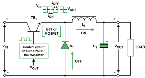
Figure 1: A forward-mode or buck step-down switching converter |
There are several different converter topologies in use, some of them more popular than others. Each has a slightly different configuration of magnetic components, such as inductors and transformers, and capacitors. Text-book topologies include the buck converter and the boost converter, and they are convenient examples to illustrate the basic principles of a switched-mode converter circuit.
A buck converter, also termed forward-mode, is used to step down the input voltage.
Figure 1 (right) shows a simplified circuit noting the use of an inductor (L) and capacitor (C) on the output circuit. The semiconductor switch (TR1) represents the fast switching action of a MOSFET driving into saturation or entirely off.
When TR1 is conducting, the diode (D) is reverse biased, and current flows to the load. This charges up the capacitor C, through the inductor (L) which opposes the flow, creating a magnetic field. When TR1 stops conduction, the magnetic field in L collapses, the diode (D) becomes forward biased forcing the current through the load, and during the same period the capacitor (C) also discharges its held charge to the load. The combination of the inductor and capacitor values create an LC filter that serves to smooth out any ripple created by the switching actions.
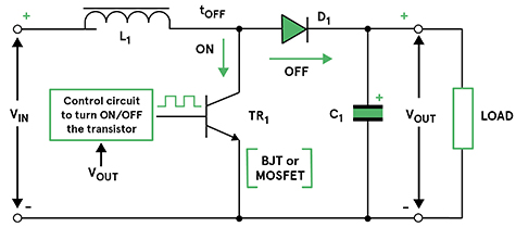
The boost converter (see Figure 2, below) is another type of popular topology, this time suiting increasing or 'boosting' the input voltage to create a higher output voltage.
Unlike the buck converter, where the switching transistor is in series with the input voltage, in the boost circuit it’s in parallel with the input and connected to the input via an inductor. The capacitor continues to be across the load, serving to hold-up the output voltage while the transistor is conducting. The inductor’s collapsing field flows to the output while the transistor is off.

Figure 2: A simplified boost converter circuit
A combination of the buck and boost topologies is the buck/boost converter that’s capable of stepping up or down the input voltage.
Note that, from an aspect of safety, none of the above topologies uses a transformer - described as a non-isolated converter - to isolate the input voltage from the output. They also share a common ground connection.
There are several topologies in use for AC-DC power supplies that provide isolation and are highly energy efficient in operation, the most popular being the flyback and quasi-resonant methods.
The architecture of a typical switched-mode power supply

Figure 3: The functional blocks of an example AC-DC switched-mode power supply (SMPS)
Input filter
The input filter serves to remove any damaging voltage transients and surges on the mains input from entering and causing damage within the power supply. The filter also aids removal of any electromagnetic interference (EMI) generated within the switching circuit from being conducted out to the AC mains.
The switching circuit typically operates from 25kHz up to 500kHz and is a source of EMI. Noise entering from the mains has two components: common mode and differential mode. Common mode relates to noise measured between either live or neutral and earth. Differential noise is between live and neutral.
A combination of inductors/chokes and capacitors form a filter arrangement to attenuate both types of noise.
Rectification
The filtered AC input voltage passes through a bridge rectifier arrangement to create a pulsating DC voltage. A smoothing 'bulk' capacitor removes line ripple from the rectified voltage and provides a voltage hold-up function.
Power Factor Correction
This is an essential aspect of any power supply design larger than 75 W - and on LED PSUs larger than 20 W - and relates to the difference between the real power used and the actual, apparent current taken, expressed as a ratio; this is the power factor.
In ideal circumstances, this ratio should be unity (1). However, the charge current behaviour of the 'bulk' capacitor used in the rectification stage distorts the sinusoidal AC mains waveform.
Passive power factor correction techniques typically use an inductor in the live input to reduce the peaks of the sine wave, reducing potential harmonic distortion and improving the power factor. However, this can reduce efficiency.
Today, most AC-DC switched-mode power supplies employ active power factor correction techniques. Often a boost converter circuit is used to control the shape of the waveform (improving the power factor) and limit the harmonic distortion.
Switching function
Comprising the switching power semiconductors, the transformer, and the driver IC, together they create a high alternating voltage for the transformer. The turns-ratio of the transformer permits a step-up or step-down of voltage, as well as serving to provide an isolation barrier.
Switching frequencies can vary from 25kHz up to 500 kHz or more. The frequency and/or the duty cycle of the PWM signal can vary depending on the load imposed on the output.
During the design of the switching function, adherence to EMI best practice is essential to minimise the conducted and radiated EMI to meet regulatory standards.
DC output and line voltage regulation
The secondary output from the transformer passes through a rectifier to the load. Smoothing capacitors and filtering components also form part of this function. The output voltage also feeds a comparator amplifier which compares the output against a reference voltage to provide tight voltage regulation.
An opto-isolator provides an galvanic safety barrier for feedback to the primary PWM drive circuit, adjusting the drive accordingly to correct any output voltage deviations.
Most switched-mode power supplies available today are highly efficient, from 85 % up to 95 % being the norm. Most waste heat generated by losses within the power supply is dissipated by conduction. However, depending on used technologies, particularly for high output power supplies delivering upwards of 150 watts, the need for forced-air cooling may be necessary.
The addition of a variable-speed fan and associated control circuitry achieves this requirement. Newer technologies though, with power up to 1500 W, all with high efficiencies, show it’s possible to move the generated heat to heatsinks or a conduction cooled ‘cold-plate’ area, avoiding the need for noisy and aging-sensitive fans. Higher power models use liquid cooling, moving away the generated heat to another area.
Selecting an AC-DC switched-mode power supply
When selecting an AC/DC switched-mode power supply, in addition to the required electrical specifications such as input and output voltage, power handling, and operating efficiency, there are several other factors on the product’s datasheet to investigate.
What is the line regulation? Most switch mode power suppliers regulate their output voltage to within +/- 3% of the stated nominal output. Is that sufficient for your end product? Also, is this maintained across all load conditions, from, say 10% load to 100 % load?
Does it have a peak output or boost capability? This useful feature permits drawing, for example, 150% of full load for a short duration. A motor start-up can benefit from this, allowing the selection of a lower-rated, cheaper power supply than having to accommodate the full peak load with a more expensive power supply.
Don't forget to make sure that the power supply meets all relevant international and country-specific regulations for energy efficiency, safety, and electromagnetic interference. Standards stipulate the minimum levels of energy efficiency at full load and 10% load, together with the maximum energy consumption during no-load conditions. In the United States the relevant standard is DoE Level VI, and in Europe, the EcoDesign 2019/1782.
Generic safety regulations include IEC 62368-1 for IT and AV equipment and, if you have a medical product, IEC 60601-1. For electric household products there is the IEC 60335-1 directive.
Additional directives include particular requirements for LED lighting, HVAC and other applications. EMI standards CISPR32 and FCC20870 stipulate the requirements of electromagnetic interference and susceptibility.
Conclusion
Specifying switched-mode AC-DC power supplies isn’t an easy task, as all the safety regulations have to be considered. Switched mode power supplies are an energy-efficient and compact method of powering any off-line end-product. They are available covering the universal AC input voltage range from 90 Vac to 264 Vac and with a variety of popular nominal DC output voltages from reputable suppliers. If you need advice on power supply selection, get in touch with our power specialists to discuss your requirements.


