
Understanding Advanced Antenna Systems
As capacity, coverage and connection density requirements grow, Mobile Network Operators (MNOs) have incorporated advanced technologies such as Massive MIMO and beamforming into their networks. In parallel, Advanced Antenna Systems (AAS) have evolved to integrate these technologies and enable their deployment in the wireless infrastructure.
Deploying the most suitable AAS variant requires an understanding both of AAS technologies, and also the specific requirements of the network. This guide provides an introduction to AAS - covering what they are, how they work, and their benefits and design challenges.
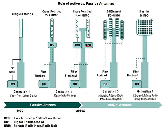 Figure 1: The evolution of antennae (Source: RCR Wireless) |
What are Advanced Antenna Systems?
Recent advances in technologies such as massive MIMO and beamforming are key to the improved capacity and throughput achievable with 5G NR. As the size of massive MIMO antenna arrays have grown, however, conventional antennas struggle to support them due to weight, space and power consumption limitations.
In a conventional antenna, for example, the RF electronics and the passive antenna are physically separate. With 100 or more antenna elements in modern arrays, it becomes unwieldy and inefficient to use separate RF cables to connect them. AAS have evolved in parallel with MIMO array developments (see Figure 1, right), leveraging advances in integration and miniaturization techniques to enable the effective deployment of 5G NR within MNOs’ network infrastructures.
An AAS combines an AAS radio with a set of AAS features, which include MIMO and beamforming. A core component of the AAS is an active antenna system, where the active transceiver array and the passive antenna array are intelligently integrated into a single hardware unit. This integration enables significant miniaturization of the AAS, whilst enhancing communication throughput, and reducing cable losses and power consumption. The AAS also includes the hardware and software required for the processing radio signals, and the algorithms to support the execution of the AAS features.
How they work
The operation of an AAS is based on a rectangular antenna array, where beamforming is used to steer high-gain beams at a range of angles. The antenna array is designed such that individual elements combine constructively to form a main lobe which transmits energy in a given direction, with the overall gain of the system dictated by the number of elements in the array. The RF signals to be transmitted are individually pre-coded, with phase and amplitude shifts, before being applied to the individual array elements - enabling them to be steered in the desired direction. The use of dual-polarized array elements, which respond simultaneously to both horizontally and vertically polarized radio waves, increases the traffic handling capacity of the system. Each element is fed by two independent transceivers, with one set on vertical polarisation, and the other on horizontal polarization.

Figure 2: Hybrid beamforming example with RF and digital steering (Source: MathWorks)
In practical AAS implementations, multiple antenna elements are partitioned into subarrays, with each subarray being fed with its own RF chain (Figure 2). This hybrid implementation requires fewer RF chains, reducing the complexity, cost and power consumption of the overall array.
 Figure 3: AOSA partitioning supports high antenna gain and steerability (Source: Ericsson) |
The characteristics of the antenna array are determined by the way in which it is partitioned into an array of subarrays (AOSA). The total antenna gain obtained when all subarray signals are added constructively, in phase, is dependent upon the number of subarrays. Two subarrays, for example, double the gain achieved over a single subarray; ie a gain of 3 dB (Figure 3A). Likewise, four subarrays add a further 3 dB but - as the size of the subarrays increase - the emitted beam becomes narrower (Figure 3B). The total gain of the antenna system is the product of the array gain and the subarray gain, as shown in Figure 3C.
In summary, the maximum gain of the antenna is determined by the number of antenna elements in the array, and the way in which the subarrays are partitioned enables steering of high gain beams over a range of angles (Figure 3C). At the same time, the subarray radiation pattern determines the envelope of the emitted beams, as shown by the dotted lines in Figure 3C.
Note that, although the above description has focused on one dimension, the same principles actually apply in both the horizontal and vertical dimensions where dual polarized antenna elements are used.
Enabling technologies
Integrated antenna arrays have been enabled by improved antenna manufacturing techniques, as well as developments in semiconductor technology. Antenna design has moved on from traditional plank architectures to flat-panel configurations which use patch antennae as building blocks. A patch antenna (see Figure 4, below) consists of a flat rectangular conductor (the patch) mounted over a larger flat conductor (the ground plane), with a dielectric material separating the patch and ground plane.
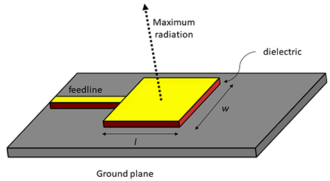 Figure 4: A patch antenna (Source: 5G Technology World) |
Patch antennae are becoming more commonly used as the wavelengths of wireless transmissions shrink. The resultant, smaller antenna geometry in turn enables the construction of antenna arrays with higher multiples of elements, leading to correspondingly higher gains.
Along with these developments in antenna design, advances in semiconductor technology have enabled the antenna electronic components - such as RF transceivers, power amplifiers, ADCs, filters and switches - to be packed into smaller ICs. These can fit onto the rear of the antenna board, significantly reducing the depth of the antenna.
With massive MIMO arrays becoming larger, and beamforming techniques more sophisticated, advanced Channel State Information (CSI) mechanisms are required to support the beam management processes. The complex software algorithms which operate on this CSI are enabled by artificial intelligence (AI) techniques, such as neural networks, which in turn are enabled by powerful custom ICs.
Active vs passive antennae
Whilst this discussion has focused on advanced digital antenna arrays, there is still a clear role for passive antennae. These systems have also evolved significantly in recent years, and are now capable of supporting 4 x 4 and even 8x8 MIMO. With many initial 5G deployments in the coverage and capacity “sweet spot” of 3.5 GHz, the full capabilities of AAS may not be required - especially in non-urban areas where capacity and user numbers are not constraints.
In these scenarios the benefits of AAS may not justify the costs, and passive systems could provide a viable alternative. Legacy networks, which will co-exist with 5G for many years to come, also use frequencies in the lower ranges, and passive antennae can be deployed to continue to support these networks.
Also, at cell sites which must deliver both 5G and continue to support legacy networks, the smaller sizes of modern antennae make it feasible to house both active and passive systems under the same radome, potentially saving on site costs and space.
Deployment scenarios
When choosing the optimum AAS configuration for a particular cell site, consideration should be given to the environment that it will be serving. Key factors include the number of users to be served, the inter-site-distances (ISDs), and the nature of the buildings and locations to be covered. The following three scenarios, illustrated in Figure 5 below, show how some of these factors influence the choice of antenna design.
|
|

Scenario A: Dense urban high-rise
Dense urban areas with high-rise buildings and large traffic volumes require large antenna arrays to ensure sufficient coverage. Partitioning the array into small subarrays gives high-gain beams that can be steered in a wide range of angles, catering for the vertical spread of users. MU-MIMO is important in this environment, and the high number of small partitions requires a sufficient number of radio chains, with 64 being a good trade-off between complexity and performance.
Scenario B: Urban low-rise
This is representative of many of the world’s large cities, with lower traffic densities, a mix of building types and less vertical spread of users. In this scenario, a large antenna area is required to deliver the required cell data-rates - but vertical coverage range can be decreased, so larger vertical subarrays can be used. MU-MIMO is still important here; but with the smaller number of subarrays, 16 to 32 radio chains are optimal.
Scenario C: Rural/suburban
These are areas haracterized by low or medium population densities, small, vertical user distributions, and inter-site distances from one to several kilometres. Again, a large antenna array is required for coverage, but vertical beamforming is not a priority - so large vertical sub-arrays are ideal. MU MIMO benefits are limited due to the low user population, therefore 8 to 16 radio chains give an optimum compromise.
AAS benefits, trade-offs, and considerations
This article has described the principles of operation of AAS, and the many benefits that they can bring to wireless networks, when appropriately deployed. The Massive MIMO capabilities of AAS are most suited to scenarios with dense user populations and high traffic volumes, where MNOs must maximise use of spectrum. The small wavelengths of mmWave transmissions enable even smaller antennas, which are ideal for network densification in these areas.
AAS are not, however, a panacea for all network deployments. MNOs must focus their investments to ensure maximum returns, and the business case varies significantly across the scale from urban to rural environments, where the sparse populations may not justify the relatively high costs of AAS. Also, legacy networks will co-exist with 5G for many years to come, and in both cases advanced passive antenna systems may be the optimal solution. These, and other factors, require careful consideration when rolling-out 5G networks.

Get support on your 5G design
Have a question, or would like to discuss your 5G design in detail? Our 5G experts are on hand to help.
Markets
5G
Whether you are developing 5G end products or infrastructure, discover how Avnet Abacus can help you find the right components for your applications.
Understanding Massive MIMO technology
An in-depth guide to Massive MIMO. Discover what it is, the different techniques involved, the benefits and design challenges of this new technology.
Read MoreHow could 5G drive growth in a post-COVID economy?
The COVID-19 pandemic has affected deployment of 5G, however it could also present a number of opportunities for the technology in a post-COVID world.
Read MoreThe evolution of cellular networks
In this review of the evolution of cellular networking, we take a brief look at previous generations of networks before examining why 5G is different and how it is expected to deliver the many anticipated economic benefits.
READ MOREThe future is 5G
5G will transform many areas of our lives by enabling further levels of innovation across multiple vertical segments, including healthcare, automotive, smart cities and industrial automation.
READ MORE