Pneumatic and hydraulic pressure sensors
Applications
Examples of systems built around pneumatic technology include vehicle tyres, air brakes (on buses, trucks and trains), air compressors, compressed-air engines, vacuum pumps and more.
Examples of hydraulic applications include vehicle braking systems, power steering systems, shock absorbers, utility vehicles such as excavators and aerial platforms, lifts and industrial machinery such as hydraulic presses.
The overarching application of pressure sensors in pneumatics and hydraulics is to ensure the pressure within the system is at the correct level, or within an optimum range.
This is particularly important for hydraulics, where the liquid in the system may be volatile or flammable (for example, mineral oil) and reach very high pressures and temperatures, making leaks and accidents potentially dangerous.
Pressure sensors feature as part of pressure regulators, or automatic valves designed to control the pressure in the system (as shown below). Pressure regulators match the demand for gas or liquid to the demands of the system, while maintaining a constant output pressure. As the system demands more power, so the load flow increases, and the regulator flow must increase, or the controlled pressure will fall.
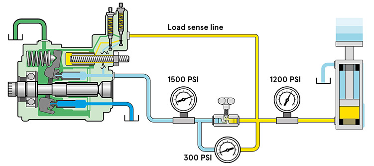
A load-sensing hydraulic system featuring three pressure sensors
Measurement options
Like other types of pressure sensor, sensors used in pneumatics and hydraulics can measure differential pressure (the difference between two pressures) or absolute pressure (measured against zero or another absolute value).
In pressure regulators, differential pressure sensors compare the pressure on either side of a valve, to determine whether the inlet flow is equal to the outlet flow.
Technology
Pneumatic and hydraulic pressure sensors are transducers, generating an electrical signal in proportion to the pressure they measure. This allows pressure to be monitored by a range of electronic devices.
The technology used most often in pneumatic and hydraulic pressure sensors uses a physical diaphragm, often made of silicon, which bends as pressure is applied to it. The diaphragm is a strain gauge, which varies its electrical resistance when force is applied – in this case, from pressure exerted by air, gas or hydraulic liquid on the sensor. This resistance is used to modify the output voltage of the sensor.
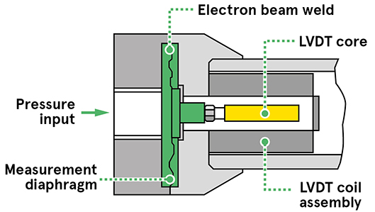
A cross-section linear variable differential transformer pressure sensor |
Some pressure sensors for power-steering applications use a linear variable differential transformer. This includes a core that moves within a hollow tube to monitor the movement of a directional control valve with high precision, allowing hydraulic fluid to flow into different areas of the system.
Many pressure sensors are now standalone, incorporating all the electronics and temperature compensation technology they need into the unit itself.
However, as the pressure used in hydraulics systems increases to drive efficiency, and systems overall become smaller and more compact, this isn’t always possible. An alternative is embedded sensors, where the electronic components are located away from the sensor itself. This allows the sensor to work in environments characterised by high temperature, vibration and radiation.
To withstand harsh environments, pressure-sensing chips have been designed such that the medium (gas or liquid) only comes into contact with silicon, helping to protect electronic components.
Some pressure sensors for pneumatics and hydraulics function by measuring the expansion of a flexible tube, rather than the pressure in the gas or liquid directly. This can help to detect blockages within the tube and monitor pump performance.
Options and specifications
Pneumatic and hydraulic pressure sensors will usually have a range of pressures they can measure – for example, 0 to 200 bar. They may also specify a safe limit of pressure, above which the unit may malfunction, and a temperature range within which they will provide accurate readings (for example, -40ºC to 85ºC).
Most pneumatic and hydraulic pressure sensors will also specify an error band – for example, ±0.05% – indicating the level of accuracy of the sensor.
Other options may include input and output connection type and output signal, as well as physical specifications such as material (including for parts in contact with liquid), dimensions and thread sizes.
Limitations
Hydraulics, in particular, are used in harsh and challenging environments involving extreme heat, water, dust and even radiation. Hydraulics on heavy vehicles may be subject to physical shocks and vibration, and may also be subject to sudden pressure spikes. Pressure sensors therefore need to be able to withstand these conditions and still function correctly.
If you want to learn more about the different types of media that pressure sensors can measure, the applications of each type, and the different sensor options for your design, click the links below to jump to the section you're interested in.
Looking for more on pressure sensor technology? Check out the further chapters of this guide below, or if you're pressed for time you can download it in a PDF format here.

